


Technical overview of the me2600 device driver
A. Driescher
This small document is a first draft of a technical oriented documentation of the
device driver. It gives you an idea of how the driver works so that you can
understand what is going on and why it is the way it is. You might want to read
this document in case you evaluate this device driver for your project and are not
sure if it fits your requirements.
After reading this document you will find answers to the questions of how
- analog to digital conversion,
- digital to analog conversion,
- reading digital ports
is supported by the driver.
The goal is to support high speed data acquisition in a none real-time
Linux environment as easy as possible. To accomplish this goal
different design decisions had to be made:
- 1. Design decision:
- The driver state is not automatically changed on
open/close system calls to allow read/write/setup tools to be called sequentially.
- 2. Design decision:
- More than one application can open the driver at the same
time, e.g. one application is writing data to the driver and an other application is
reading data. While these both programms are running a third can use ioctl
to change settings.
![[*]](file:/usr/lib/latex2html/icons/footnote.png)
- 3. Design decision:
- More than one application can read data from the driver without
interfering with an other reader. This allows you to run your main application while
a simple monitoring application runs in parallel.
- 4. Design decision:
- The driver should support buffering for data acquisition
for a user defined time. (The buffer size is configurable at compile time and
only limited by the available memory.)
- 5. Design decision:
- The data stream produced by the driver should be self contained.
This means that reading a single sample from the data stream allows you to determine where it came
from (which ADC channel), what settings had been used to get this datum (e.g. gain of the ADC channel)
and what time stamp belongs to this sample. The advantage of this approach is that handling the
data stream in you application is much easier but it comes at the cost of wasting more memory
and processor bandwidth because settings like gain, polarity etc. are normally not changing
at all after you have once set it for your problem.
The device driver design is based on the ``normal'' understanding of the
Linux file system interface. This means that read aud write are
used to read data from the analog to digital converter or write new
values to the digital analog converter, respectively. How exactly the data
conversion is handled can be set by the ioctl system call of the driver.
This mean for instance that a command like
cat /dev/me2600_aio | gzip my_data
could be used to read date from the device driver and write these data in compressed format to a file that
could be processed later on.
AD conversion is based on the following model:
- The ADC is initialized by setting polarity, gain and ending for every
channel.
- The conversion mode is set to single, multiple or endless conversion.
- The trigger mode is selected to tell the device what event starts the conversion.
- When a trigger event is recognized the event is written as an
event block to the ring buffer followed by data blocks containing the
result of the conversion.
Depending on what conversion mode you have chosen, a trigger event can
cause one of the following results: A single data read, reading a given
number of samples or starting an endless conversion with the sample
time of me2600 on board hardware clock. The trigger event itself can
be either a software command or an external trigger event (pin 51).
All data (the results of the ADC, the events and also digital I/O values)
are written to a ring buffer interface, that can be read by the usual read() function.
The data in this ring buffer are well defined data blocks. Each data block contains
a header about the data block size, the driver version used to produce the data,
a block sequence number and what kind of data is contained in the data block.
After the header, the ``useful'' information, e.g. the result of the ADC or
the state of the digital I/O is sent.
typedef struct{
        // header for all blocks
        unsigned int block_size;                        /* size of this struct */
        unsigned int driver_version;                    /* internal version number of this driver */
        unsigned int block_sequence_number;             /* sequence number of this block */
        block_type type;                                /* type of data block */
        // variant data block dependig on "type"
        union {
                unsigned int data_sequence_number;      /* sequence number within this block type */
                adc_data_v1 adc_v1;
                dio_data_v1 dio_v1;
                event_data_v1 event_v1;
        } data;
} block_struct;
A central problem is the assignment of time stamps to the measurement. The me2600 hardware
does not automatically assign time stamps to measurements. The nearest thing to a time stamp
is the interrupt time generated by the hardware for the ``convertion ready event''. Naturally,
the jitter is therefore based on the interrupt latency in your computer. The me2600 can generate
two different conversion ready interrupts. The first is after a single conversion is ready;
the second is given at the FIFO half full event. While for small sample frequencies one interrupt
per conversion is no problem, the hardware can support a sample frequency up to 300KHz.
Without real time kernel extentions this interrupt rate is unlikely to work reliable.
In this case it is certainly more appropriate to generate an interrupt after the
FIFO is half full to reduce the interrupt frequency to something the kernel
can handle.
Depending on how fast the computer is, how high the system load is and what interrupt
has been choosen by the user, data can be lost due to some overflow condidition either
in the onboard ADC-FIFO or the driver's ring buffer. What exactly the best error
handling strategy is, is application depending. The driver supports error detection by:
- sending status information in every event block,
- maintaining a block/sequence counter for the data blocks.
The block counter allows easy detection of ring buffer overflows.
If the number of a block is not equal to the number of the last block plus one
a buffer overflow occurred.
The internal data processing algorithm at interrupt time is as follows:
- Save the interrupt time temporarily.
- Determine the interrupt source (either FIFO half full or single conversion ready).
- Check and save possible error conditions signaled by the me2600 hardware.
- Write an event block containing interrupt time stamp, interrupt source and
error conditions to the ring buffer.
- Read data from ADC-FIFO until the ADC-FIFO is empty and write all data as
data blocks to the ring buffer.
The me2600 hardware supports  analog output channels. Each channel can be independently configured
to one of the following output ranges:
analog output channels. Each channel can be independently configured
to one of the following output ranges:
 ,
,
 or
or
 .
A ioctl command is provided by the device driver to configure the channels according to
your needs.
.
A ioctl command is provided by the device driver to configure the channels according to
your needs.
To change the output of one or more of the channels you have to write a struct to the device interface
that looks like that:
// definition of possible data block types for write interface
typedef enum{do_block_v1, da_block_v1} write_block_type;

typedef struct{
        // header for all blocks
        unsigned int block_size;      /* size of this struct */
        write_block_type type;        /* type of data block */
        union {
                do_data_v1 do_v1;
                da_data_v1 da_v1;
        } data;
} write_block_struct;
where da_v1 contains the data for the channels. This struct is defined by:
 typedef struct{
        short       value[ME2600_NUM_DA];  // value to write to the DA
        me2600_bool valid[ME2600_NUM_DA];  // !=0 -> update the corresponding port
        me2600_bool update_now;            // True=update DAC in buffered mode, ignored in transparent mode
} da_data_v1;
So, programming the DAC boils down to:
- write the desired output voltage (encoded as 12 bit values) to the value field for every channel you
want to update.
- Mark the channels you want to change in the valid field by setting the corresponding entry to anything not zero.
- Set update_now to true to make sure your changes will really happen (or set the driver into transparent mode).
The following sections discuss typical application examples that might be relevant for
the user. At least this is what the developer had in mind when writing the driver.
The driver has useful default settings for data acquisition tasks
requiring a low sample frequency with limited timing precision. This
mode is automatically chosen after the driver has been installed. A
typical example would be the measurement of one or more signals every
second where a small jitter in the sample time (e.g. 10ms) does not
matter. The default setting of the driver is to expect the signals in
the range
for differential mode.
Every time an application tries to read data from the driver the conversion is
automatically started. So, the read timing simply depends on
when the caller reads data from the driver. In this mode all 8
channels are used resulting in a conversion time of
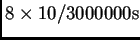 because every channel needs 10 clocks generated
by the me2600 oscillator at
because every channel needs 10 clocks generated
by the me2600 oscillator at  to finish its conversion.
The sample frequency and timing accuracy depends only on the caller as
long as the required conversion time plus a small processing overhead
in the device driver can be neglected. Due to the none-real-time
characteristic of Linux, sample frequencies larger than
to finish its conversion.
The sample frequency and timing accuracy depends only on the caller as
long as the required conversion time plus a small processing overhead
in the device driver can be neglected. Due to the none-real-time
characteristic of Linux, sample frequencies larger than
 are difficult to manage with this driver
configuration as long as a reasonable small timing jitter is required.
are difficult to manage with this driver
configuration as long as a reasonable small timing jitter is required.
Burst sampling
Burst sampling means getting a finite number of samples after the
conversion started with possibly a high sample rate. When the required
number of samples have arrived the conversion is stopped and the
application has now time to process the data.
The driver supports this mode by allowing the user to setup the number
of requested samples and the sample frequency.
Due to a hardware bug in the me2600 the driver has to wait until at
least  samples have arrived (FIFO half-full interrupt) even if
you have requested a smaller number of samples. This can cause an
undesired latency time that is especially relevant for smaller sample
frequencies.
samples have arrived (FIFO half-full interrupt) even if
you have requested a smaller number of samples. This can cause an
undesired latency time that is especially relevant for smaller sample
frequencies.
Example:
Let's say you want a sample frequency of
 . Assuming
 channels are sampled, the latency is
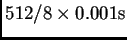 plus conversion time. This means that the conversion result will at
the earliest be available after
plus conversion time. This means that the conversion result will at
the earliest be available after  even if you only need
 sample. The work around is to increase the sample frequency until
an acceptable latency time is reached and than throw away unnecessary
data.
sample. The work around is to increase the sample frequency until
an acceptable latency time is reached and than throw away unnecessary
data.
In streaming mode (also called endless conversion mode) you simply
tell the driver the desired sample frequency and which channels you
want to process. After the next trigger event the ADC endlessness
converts the input signal with the given sample frequency. The driver
writes new data into a ring buffer where the application is
responsible to get these data quick enough to prevent a buffer
overflow. This mode is for instance useful for multi channel audio
processing because the time interval between samples is not determined
by the application but by the me2600 on-board hardware
clock. The latency
concideration from section ![[*]](file:/usr/lib/latex2html/icons/crossref.png) hold for this mode
as well but are usually of less importance because this mode is
usually used with high sample rates.
hold for this mode
as well but are usually of less importance because this mode is
usually used with high sample rates.
Technical overview of the me2600 device driver
This document was generated using the
LaTeX2HTML translator Version 99.2beta8 (1.43)
Copyright © 1993, 1994, 1995, 1996,
Nikos Drakos,
Computer Based Learning Unit, University of Leeds.
Copyright © 1997, 1998, 1999,
Ross Moore,
Mathematics Department, Macquarie University, Sydney.
The command line arguments were:
latex2html -split 0 technical_overview.tex
The translation was initiated by Arne Driescher on 2003-06-06
Footnotes
- ... settings.
- This is most useful if one application is reading data while
triggering the data acquisition is done by and other program via ioctl.
- ... problem.
- From a technical point of view the 2. design decision implies
the 5. design decision.
- ...
- Please read the relevant chapter in the original Meilhaus
manual (also available at http://www.meilhaus.de|) on how
the electrical connections have to be done.
- ...
clock.
- In this way the sample frequency remains constant
independently of what your PC is currently doing.
Arne Driescher
2003-06-06